How to configure OSPF Routing Protocol
OSPF is a routing protocol. This tutorial explains how to configure it on Cisco routers. It uses Packet Tracer network simulator software to explain OSPF configuration steps. You can use any simulator software or real routers to follow these steps. These steps are the same on all platforms.
OSPF configuration practice involves the following steps.
- Creating a practice lab and assigning an IP configuration to all interfaces
- Testing connectivity between all interfaces
- Enabling OSPF routing on all routers
- Verifying and testing OSPF configuration
Creating a practice LAB
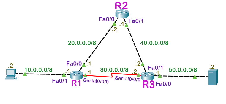
Add three routers, one PC, and one Server to the workspace. Connect devices and assign an IP configuration as shown in the following image.
Alternatively, you can download this lab from the following link.
Testing connectivity
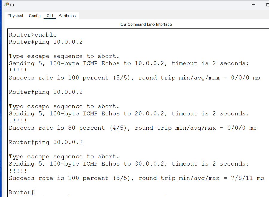
You can use the ping command to test connectivity. A ping command reply verifies devices have connectivity.
Testing connectivity from R1
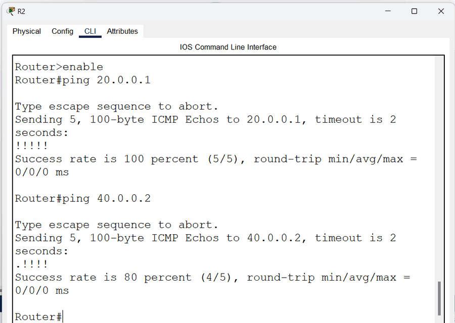
Testing connectivity from R2
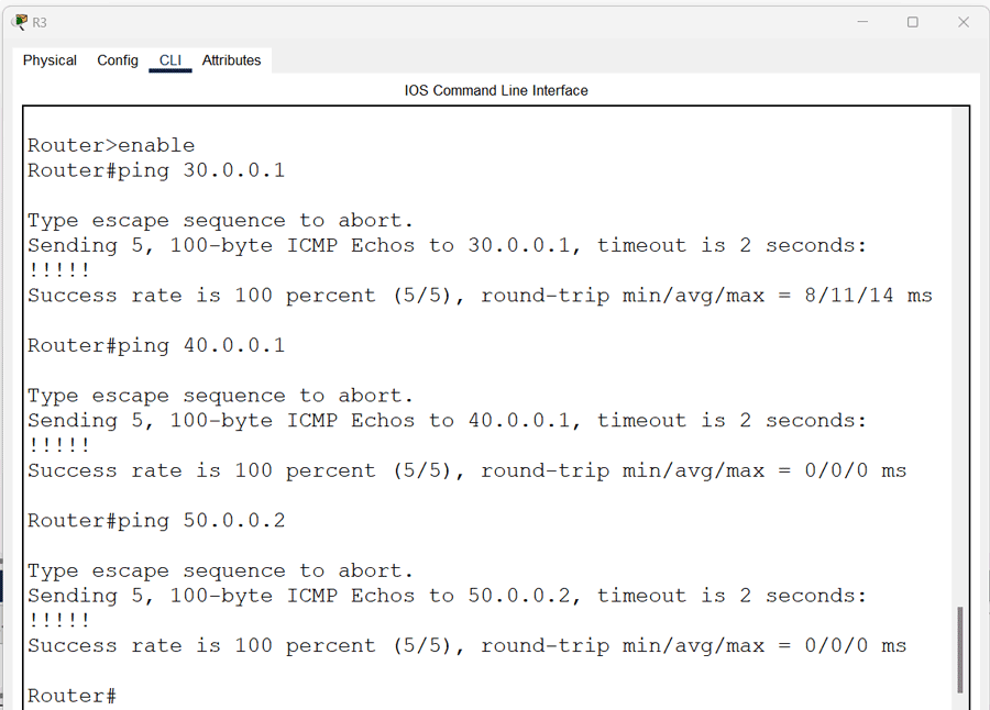
Testing connectivity from R3
OSPF Routing commands
The following two steps in global configuration mode enable OSPF routing on the router.
- Enable an OSPF process.
- Assign an area to the interfaces.
The following command enables an OSPF process on the router.
Router(config)# router ospf [process_ID]
Process_ID
You can run multiple OSPF processes on a single router. The router uses the process_ID to differentiate between OSPF processes. The process_ID is a numeric value. It can be any number from 1 to 65,535. It is locally significant. You do not need to match it on all routers. You can use a different process ID on each router. The following command assigns an area to the interface.
Router(config-router)# network [IP_network_#] [wildcard_mask] area [area number]
Each router interface requires a valid IP address to function correctly. This command matches the given IP address with the IP address of all interfaces. If an interface's IP address matches the given IP address, it enables the OSPF process on that interface and adds that interface to the specified OSPF area.
You can use a wildcard mask to match multiple interfaces with a single configuration line. A wildcard mask tells the router the part of the address it should match. It contains wildcard bits. In binary, 0 is a matching bit, and 1 is an ignoring bit. In decimal, number 0 represents a matching bit while number 255 represents an ignoring bit. For example, the mask 0.255.255.255 indicates a match in the first byte of the network number.
The area ID is the area number for which you want to configure this interface. It is an integer between 0 and 4294967295. OSPF uses areas to limit the routing information routers share. It divides routing information into two types: detailed and summarized. Routers share detailed information only within the same OSPF area. Routers in different OSPF areas share only summarized information. They do not share detailed information. OSPF areas are interface-specific. A router's interfaces can run in separate OSPF areas. Area 0 has a special meaning. OSPF uses it as the backbone area. All OSPF areas must connect with it. It is a compulsory area.
OSPF single-area configuration
OSPF single-area configuration keeps all routers in a single area. Since area 0 is compulsory, a single area OSPF configuration includes only area 0. A multi-area configuration includes more than one OSPF area. This tutorial configures OSPF in a single area.
Enabling OSPF routing
Enabling OSPF requires a process ID. Process ID is locally significant. You can use the same process ID on all routers or choose a different ID on each router. Keep all routers in area 0 and use a different process ID on all routers.
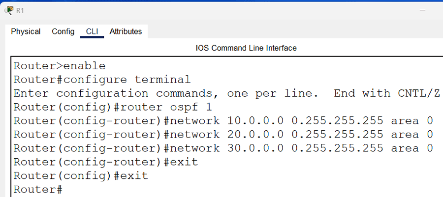
Enabling OSPF Routing on R1
The following commands enable OSPF routing on R1.
Router>enable
Router#configure terminal
Router(config)#router ospf 1
Router(config-router)#network 10.0.0.0 0.255.255.255 area 0
Router(config-router)#network 20.0.0.0 0.255.255.255 area 0
Router(config-router)#network 30.0.0.0 0.255.255.255 area 0
Router(config-router)#exit
Router(config)#exit
Router#
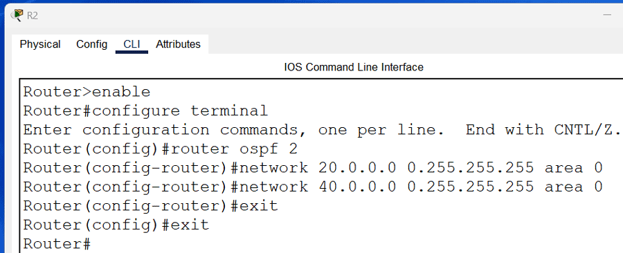
Enabling OSPF Routing on R2
The following commands enable OSPF routing on R2.
Router>enable
Router#configure terminal
Router(config)#router ospf 2
Router(config-router)#network 20.0.0.0 0.255.255.255 area 0
Router(config-router)#network 40.0.0.0 0.255.255.255 area 0
Router(config-router)#exit
Router(config)#exit
Router#
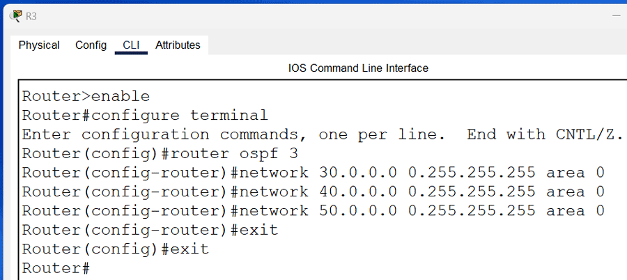
Enabling OSPF Routing on R3
The following commands enable OSPF routing on R3.
Router>enable
Router#configure terminal
Router(config)#router ospf 3
Router(config-router)#network 30.0.0.0 0.255.255.255 area 0
Router(config-router)#network 40.0.0.0 0.255.255.255 area 0
Router(config-router)#network 50.0.0.0 0.255.255.255 area 0
Router(config-router)#exit
Router(config)#exit
Router#
Download Packet Tracer LAB with OSPF Routing
Verifying the OSPF routing
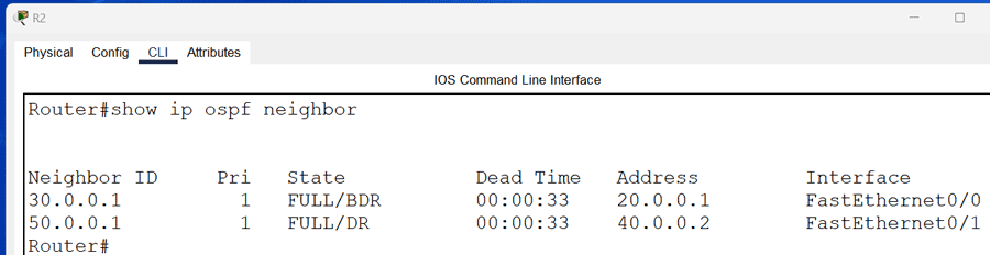
OSPF shares routing information only with neighbors. Use the show ip ospf neighbor command on R1 to verify OSPF neighbors.

The output includes the following fields.
Neighbor ID
This field displays the RID of the neighbor.
State
This field displays the convergency state. An OSPF router goes through seven states to reach convergence. The Full state in this field verifies that the router has reached convergence with the router listed in the neighbor ID field.
Interface
This field displays the local interface connected to the neighbor.
Address
This field displays the IP address of the neighbor.
Dead time
This field displays the dead interval.
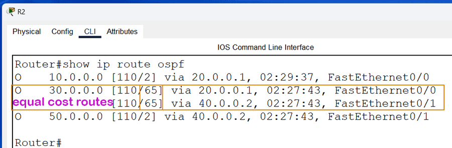
The following image shows the output of this command on R2.
The following image shows the output of this command on R3.
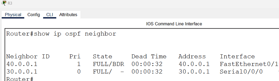
Viewing OSPF routes
The show ip route ospf command displays a list of all OSPF routes in the routing table. The following image shows the output of this command on R1.
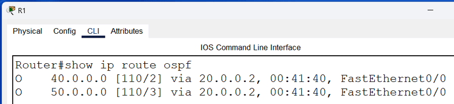
If multiple routes to a destination exist, OSPF adds only the fastest route to the routing table. If two or more routes have an equal cost, it adds all added to the routing table. It uses them for load balancing. For example, R2 has two equal-cost routes for the network 30.0.0.0/8. It adds both routes to the routing table.
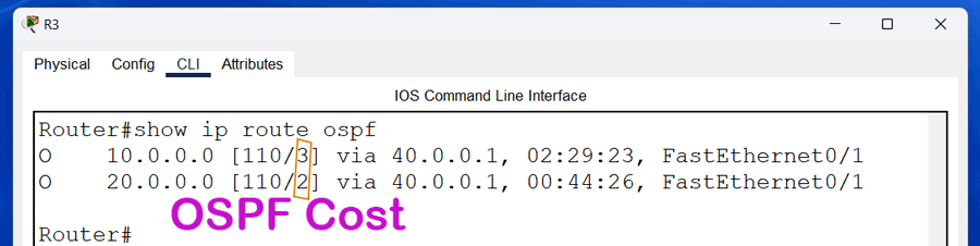
The following image shows the output of the show ip route ospf command on R3.
Testing connectivity between end devices
You can test connectivity between end devices to verify the OSPF configuration on all routers. Send ping requests from the PC to the Server. If it gets replies, it verifies the OSPF configuration. You can also use the tracert command to print the path the data packets take to reach the destination.
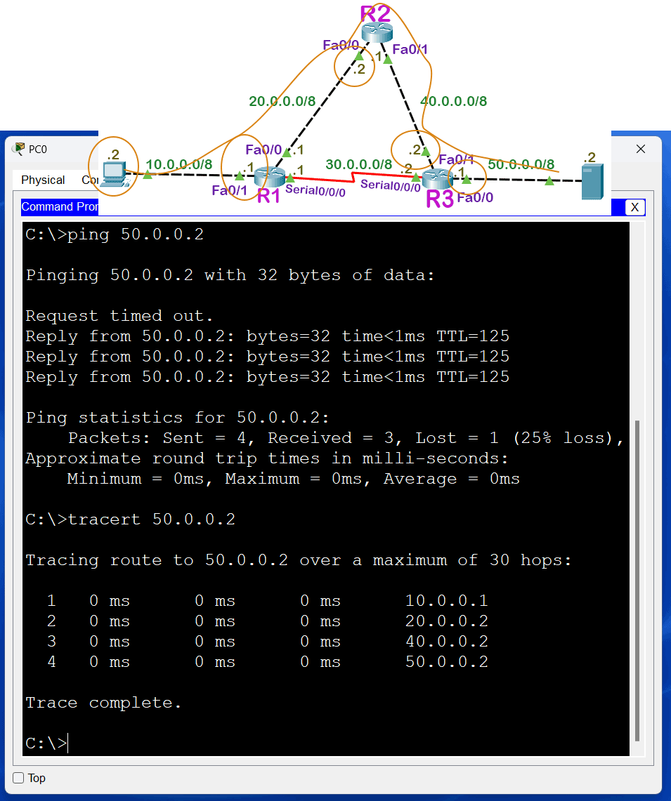
R1 is the default gateway for the PC. It has two routes to reach the network 50.0.0.0/8: a direct route and via R2. It forwards data packets through the second route. The first route has a serial and an Ethernet link. The second route has three Ethernet links. A serial link with default bandwidth costs 64. A 100 Mbps Ethernet link with default bandwidth costs 1. The total cost of the first route is 3 (1+1+1). The total cost of the second route is 65 (64+1). OSPF selects the route that has the least cost.
This tutorial is part of the tutorial "OSPF Configuration and Concepts Explained.". Other parts of this tutorial are as follows:
Chapter 01 OSPF (Open Shortest Path First) Protocol
Chapter 02 RIP V/s OSPF | Differences between RIP and OSPF
Chapter 03 IGP, EGP, and Autonomous System Explained
Chapter 04 OSPF Features, Advantages, Disadvantages
Chapter 05 OSPF Fundamental Terminology Explained
Chapter 06 OSPF LSA Types and LSA Flooding Explained
Chapter 07 OSPF Area Types and Concept Explained
Chapter 08 OSPF Hello Protocol and Packets Explained
Chapter 09 OSPF RID (Router ID) Explained
Chapter 10 OSPF Neighborship Condition and Requirement
Chapter 11 OSPF DR BDR Selection Process Explained
Chapter 12 How OSPF Routers Build Adjacency Explained
Chapter 13 Shortest Path First (SPF) Algorithm Explained
Chapter 14 OSPF Single-Area Configuration Explained
Chapter 15 OSPF Stub area, Totally Stub area, NSSA, and Totally NSSA
Chapter 16 OSPF Virtual Links Explained
Chapter 17 OSPF Authentication Password and MD5 Explained
Chapter 18 OSPF Multi-Area Configuration Explained
Conclusion
This tutorial explained how to configure, test, and verify OSPF configuration on Packet Tracer. Learning these steps helps you implement and manage the OPSF routing protocol on a live network.
Author Laxmi Goswami Updated on 2026-05-11